
Monday 30 April 2012
Point To Point Tube Screamer
this is one of my over the top efforts to prove that a turret board Tube Screamer would sound bollocks all different to a normal one - at the time Ibanez had just released a turret board version of the tube screamer at an extremely inflated cost - so I took one apart and copied it and as I suspected, it sounded no different - still, audiowank aside (and I'll include some of the COMICAL sales shit at the bottom) - turret board construction is fun so here you go.
there are a few confusing abbreviations I have used (for some reason) so I will try and clear it up best I can.
(VR) is Voltage Reference - these are supposed to be connected to each other
where you see a number in brackets eg (1) this denotes that it should be connected to the same number at any other points on the board.
V1 V2 V3 - refers to the Volume Potentiometer
T1 T2 T3 - refers to the Tone Potentiometer
D2 D3 - refers to the Drive (gain) Potentiometer

The Ibanez TS808HDW Hand Wired has a Select 4558D IC Chip - yeah so does mine, I picked it up out of the little draw, the hard decision came when I was trying to choose between that one and another one with a slightly bent leg
This one is hilarious...
the incomparable overdrive pedal thats been described as "the Holy Grail of Tube screamers." Our 2004 TS808 reissue features the same famous standout square footswitch of the original and the even more famous warm tones of the JRC4558 chip used in most of the original TS808s. Ignore any over-the-counter lookalikes. If your tone is suffering from a lack of real warmth, the TS808 is the real, non-generic prescription.
and this..
The TS9DX Turbo Tube Screamer features the slightly warmer JRC4558D IC found in most of the old TS808
they keep talking about the IC being "warm" I had a JRC4558 IC that was warm, in fact it was hot, but that was mainly because I was putting 2000 volts through it. it also achieved the greatest transparency I've ever known from an op-amp, you could see through the hole that was blown through it.
the simple fact is that in this kind of device the op-amp you use is going to make sod all difference unless say the op-amp has a drastically different gain characteristic or output current. this is one of those traps for idiots who go to eBay to buy a NOS JRC4558 for £30 a go! shit, I bought 4558's when I couldn't afford more reliable ones!
the RC4580s are good ICs for real audio as it was designed for audio applications - with quite a high gain bandwidth of 12MHz and around 50mA of output current - if I were going to spend £30 I would just buy a box of 4580s or get them for free by taking apart literately anything that has audio involved with it - old DVD player etc.
Voltage Inverter With 555 IC Stripboard Veroboard
I can't remember why I did this or even when I did it but I did do it, it was quite possibly something out of The Art Of Electronics but I can't be sure - anyway I'm guessing I needed a -5v supply for something and I was too cheap to buy a 7660 or MAX1044 charge pump


Curious C-Beeper Stripboard Veroboard
this is a cool little piece of test gear that I made after seeing one of Alan Yates' videos - you should go and watch the video and I'm sure you'll want to build one too.

 |
| reposted without permission - because I couldn't find a contact to ask |
Instrumentation Amplifier Stripboard Veroboard
this is not a complete project, I did this to kind of interface an Instrumentation Amplifier with various sensor ideas - the interface works and is a good little experiment platform


Arduino (for extra blog cred) Stripboard Veroboard
I did this sometime ago when I was flirting about with uControllers, needless to say I grew bored of them pretty quickly because it's not really electronics, it's programming and I hate programming however I did a few projects that I wanted to keep and make permanent so I did a stripped down veroboard of the Arduino board. essentially it powers and allows you to interface with the uController I/O's - has a "sketch" reset switch, a main power LED and a flasher LED (if you want to run the LED flasher "sketch")


Simple Adjustable Bench Power Supply Stripboard Veroboard
here is the schematic/layout I made up for it - it's a bog standard LM317 circuit which I made a few additions to, I used a 1k multiturn potentiometer and a 121r resistor to give me a maximum output voltage of about 11 volts
you can also use the extremely common 1117 adjustable regulator - it only gives out 800mA but the beauty of this IC is that it's in just about everything (usually surface mount)
I also added the power supply needed for the display (layout can be found in the blog under "7107 voltmeter")


EMG Active Preamp for 81/85 pickups Stripboard Veroboard
I recently got a LTD les paul type guitar and it came with the EMG-HZ passive versions of the 81/85 pickups so I searched the internet for a schematic of the preamp circuit and found one, made a verolayout for it and then put it in my guitar and it's pretty cool - here is a song I used the guitar with the preamp in


Dual Op-Amp Tester /Signal Generator Stripboard Veroboard
I bought a ton of LM358s from China (grey market IC's) so I wanted to make sure they all worked - I figured the best way to do that was to make a rudimentary signal generator that outputs a triangle and a square wave.
I've included scope settings so you can easily see if the IC is working or not.


Mains Finder Stripboard Veroboard
a quick brutal mains finder stick thing - in close proximity to mains it will cause the LED to flash - I've used a weird type of layout in order to stick it in a tube


Buffered Y Splitter Stripboard Veroboard
as an engineer of music one of my biggest frustrations has always been guitarists and "EQ creeping" because they never realize that to get the best results through a microphone you have to severely reduce the EQ settings that you would normally use because what you hear from across the room is much different to what a microphone hears at the sound source - so what happens is that you set the amplifier up for recording, the guitarist would think "that doesn't sound like it normally does, I better adjust it because it won't sound good on the recording" and usually when you aren't looking they go over to their amplifier and turn the mid down and the treble and bass up this is the phenomena of EQ creeping, it becomes a problem when you set up everything to sound good on a recording only to find after recording a whole ton of tracks it isn't to be a nightmare of EQing because of the EQ creeping that has gone on.
so in order to combat this I made a simple little Y box (or Why do they not listen box) which I use without their knowledge so that it records whatever turd they think sounds good from the amp and a separate signal directly from the guitar allowing me to set up an amplifier after they have pissed off to tell their mates how they "laid down some sweet tracks today and it's going to sound awesome cause I helped engineer it"
so if you have ever been annoyed by "musicians" using the practice of EQ creeping - this is for you.
it needs to be buffered because a very low voltage signal is being split to 2 outputs


Theremin Stripboard Veroboard
quite a nice sounding little theremin - I even had PCBs made up for this one cause I loved it so much but for you here are the veros.
make sure that you do not ground the antenna by attaching the antenna to a metal project box like I accidently did cause it won't work, it is advisable to remove
all unused copper tracks to reduce any noise.
it only draws 65mA so you can use one of the smaller transistor sized voltage regulators with no heat issues.


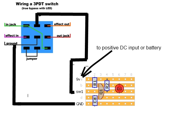
Red On Green Off for selector swtiches
a Quick little circuit - essentially it is an inverter which changes the polarity depending on the state of the switch, as I used it in a guitar effect primarily (quite a few other things since) I made a few pictures up to show how to connect it to a guitar pedal switch


Balanced to Line Microphone Preamp VeroBoard Stripboard
this is a nice high quality microphone preamp without all the added audiowank you usually see on these things - it uses quite expensive parts mainly because I got them as free samples from Texas Instruments.
I recorded a few songs with it - acoustic ones in order to show what it's like on acoustic guitars because that's where it excels
you can of course add phantom power to this however you need to add it pre- the diodes (they are there to protect the instrument amplifier IC) and you also need to make the 2 input caps (C1 C2) non polarized ones


Boss OD1 14 Pin Version Stripboard Veroboard
a guitar overdrive, quite a nice one - it uses a quad op-amp this buffers the input and output signal before/after it's passed through the overdrive which makes your guitar quite responsive but not with over the top overdrive.
this is one someone asked me to make for them - they wanted the "14 pin version" and not the "8 Pin version" basically Boss decided to reissue this pedal without the buffer parts - most probably because the op-amp they used had a none standard pinout to a jellybean one like a LM324 and instead of redesigning the board to use a different quad they redesigned the board to use a dual op-amp, I'm not entirely sure what the thinking was there but here is my version which is a quad op-amp version to use a normal quad op-amp.

IR Flip Flop switch Stripboard Veroboard
this is a little design I did when trying to figure out a way to turn the light on and off from across the room with a remote control, the drawback to it is that it reacts to any IR remotes but after I made this I replaced the sensor with a hacked off bit of dvd player (the bit with the IR sensor stuff in it) so it now only responds to a few buttons on the remote that belonged to the old DVD player.
for me solutions are better when they are free - I don't care if it looks like shit.

for me solutions are better when they are free - I don't care if it looks like shit.

Atomic Clock
just a small "on a whim" eBay purchase - a rubidium clock which was (literately) sawn off an old mobile phone tower.
not really much in the way of electronics all I built were power supplies really but I think it's a cool little project and I use it to sync my midi/digital equipment - not that you need an atomic clock to do that but it cost £40 and all those weird audiophiles will love it.
on the datasheet for this thing, it had a note saying that it's locked into it's super-accurateness when the output goes low on the indicator output. so I made a little transistor switch to light an LED when it goes low
edit: whilst looking up some info on RF I came across this site which has some brilliant information on how to adapt your own version of this very atomic standard Rubidium Standard


Technical Manual
Constant Current Dummy Load VeroBoard Stripboard Veroboard
Similar to the one Dave uses


7107 LED Voltmeter Stripboard Veroboard
based largely on articles in The Art Of Electronics I came up with this layout for a DVM based on the ICL7107 DAC I ended up doing 2 different layouts - one with a built in power supply to give me the +/- 5v needed and one that is just the meter circuitry alone.
in the Datasheet - the 7107 calls for the use of a 100pf capacitor however I found this to be far too slow at responding to a multiturn pot in a power supply so I replaced this with a 10pf capacitor which was much much better - meaning of course you don't have to mess about with trying to get accurate readings from the adjustable power supply (if you use it in one) if you build it - try to ignore the displays I've put on the first picture - they were for my reference and it was possibly a very specific display (I tend to use salvaged junk)
I've also included a couple of pictures of things I've used it in.
 |
| Add caption |

 | |
| Display wiring layout |


Subscribe to:
Posts (Atom)